Redundancy Modeling in Critical-Facility Configurators
Redundancy labeling without enforcement is just paperwork, not protection.
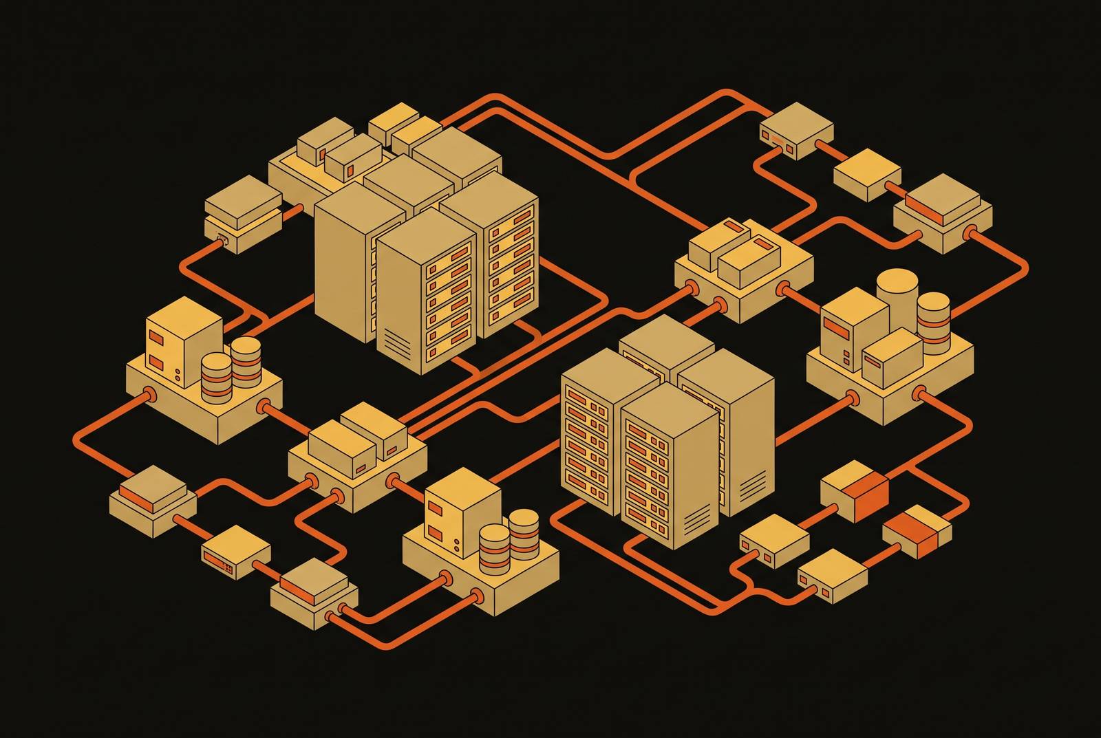
N+1 and 2N sound like technical labels. In practice they're promises about what happens the moment a component fails, and most configurators only keep half that promise. A configurator that lets someone pick "N+1" or "2N" from a dropdown and then stops paying attention is just recording a label, not enforcing an outcome. Real redundancy modeling turns that tier selection into a rule set governing every power path, every cooling assignment, and every cable route from that point forward. It catches violations the moment someone tries to enter them, not months later during commissioning, and that timing difference is the whole point.
What each redundancy model demands from a configuration, domain by domain
N+1 means minimum capacity plus one standby unit. If a facility needs N units to serve full IT load, the configuration needs N+1, and that extra unit has to sit on a path someone actually checked, not just penciled in on a drawing. 2N goes further: two fully independent systems, each able to carry 100% of the load on its own, with no shared point of failure between them anywhere.
On the power side, the obligations scale directly with tier. N+1 calls for one utility feed, one generator set, one UPS string, with a standby that's been verified. 2N calls for dual utility feeds, dual generator sets, dual UPS strings, and dual PDUs to every rack, with no shared failure point anywhere in the chain. 2N+1 takes all of that and adds one more unit at every layer, wired in, commissioned, and provably ready to go. Not paperwork. Actual, tested availability.
Cooling follows the same logic, but the math is where people cut corners. N+1 means one extra CRAH or chiller unit past the minimum, and that minimum has to come from worst-case IT load, not whatever the facility runs on an average Tuesday. 2N means two cooling loops that can each carry the full load independently, with chilled water piping, pumps, and controls kept separate the entire way through. As rack densities climb past what used to count as normal, especially with liquid cooling entering the mix, the redundancy math on cooling gets a lot more tangled. Manifold branching, leak detection, secondary loop independence: these are redundancy-model questions now, not just capacity questions.
Cable and network routing rounds out the picture, and it's the domain most likely to get waved through as a formality. That verdict belongs with the point it is judging: cable and network routing is actually the domain where separated paths matter most, not one to be waved through as a formality. Cable and network routing is the domain most likely to get waved through as a formality, but a single tray failure can't be allowed to take out both the A side and the B side at once. A 2N configuration needs physically separated cable paths: separate conduit, separate trays, separate entry points into the building. Redundancy has to run through the whole workflow as governing logic, not sit off to the side as a checkbox.
None of these three domains work in isolation. A rack fed by dual PDUs needs dual cable paths and matching cooling capacity on both sides. One redundancy choice activates all three constraints at once, and if any single one fails, the effective tier of that rack drops, whatever the project spec still claims on paper.
Late discovery gets expensive fast. For large organizations, outage cost runs around $9,000 a minute, roughly $540,000 an hour, and in finance or healthcare that figure climbs past $5 million an hour. A misconfigured power path caught during commissioning carries exposure measured in those numbers, and Uptime Institute's Annual Outage Analysis 2025 found that nearly 40% of organizations hit by a major outage over the past three years traced it back to human error. That's precisely the failure category deterministic rule enforcement exists to catch, at the design stage, before it turns into a statistic.
Encoding redundancy as deterministic rules: a non-negotiable requirement, not a design preference
AI and deterministic rules need to stay in their own lanes here, and blurring them is where most of the damage gets done. AI-driven layout suggestions and capacity optimization make sense where flexibility is the goal, and nobody should ask them to do less. But redundancy topology enforcement is a compliance and safety problem, and probabilistic output is the wrong tool for that job. Full stop.
There's a real difference between an advisory flag and a hard stop, and most tools quietly pick the weaker one. A flag tells someone there's a problem and lets them click past it anyway. Swap an approved UPS model for a different unit with different transfer characteristics mid-project, and the redundancy topology looks unchanged on paper. The actual failover behavior shifts underneath it. Only a hard stop keeps the model honest.
The common failure mode looks like this: a designer lays out a full rack configuration, then tags the project "2N" as a label. Nobody checks that every rack actually got dual PDUs, that the power paths stayed physically separated, or that cooling wasn't quietly shared somewhere in the loop. The label reads fine in the document. It's marketing, not engineering, and it fails exactly when someone needs it not to.
Tier IV raises the stakes further. It requires fault-tolerant design that absorbs any single unplanned equipment failure or distribution interruption without touching IT operations, on top of inheriting Tier III's concurrent maintainability requirement. None of that holds if the configurator ever lets components get shared across paths meant to be independent, even briefly, even during a routine maintenance window.
Equipment parameters, power path assignments, and cooling zone allocations need to flow straight into DCIM, EPMS, and BMS integration instead of getting manually re-typed into a separate system somewhere downstream. That's how the redundancy model survives the handoff into operational visibility instead of getting lost between the design team and the people running the facility.
Translating a redundancy tier selection into cascading design rules
The tier gets picked once, at the project or zone level, and that single choice should trigger a full rule set covering everything that follows in the session. No exceptions carved out for convenience.
On power, a 2N selection should force two PDUs per rack, verify each sits on an independent busbar, and flag any single-corded rack as non-compliant before the designer moves forward. An N+1 selection should check that for every N units specified, N+1 actually show up in the configuration, with the standby on a real, routed path rather than a number sitting in a spreadsheet cell. The configurator should trace the full chain: IT load back through PDU, busbar, UPS, transfer switch, generator, all the way to the utility feed. Any gap anywhere in that chain should block the session, not just flag it for later.
Cooling rules follow the same logic. Capacity gets calculated against full IT load, never average load, so N+1 means N units running at full load plus one spare, not N units running comfortably with a cushion built in. For 2N, the configurator has to confirm the two loops don't share chillers, pumps, or controls, because shared components quietly collapse what's labeled 2N into something that behaves like N+1 the moment anything actually fails. The cooling path needs to check out spatially too: a CRAH unit assigned to a zone it physically can't reach doesn't count as redundant capacity, no matter what the label on the drawing says.
Cable routing rules enforce physical separation directly. A-side and B-side fiber routes need to run in separate trays with zero shared segments, and a route crossing into the same tray at any point is a separation violation, flagged the instant it happens. Bend radius, clearance, and separation all get enforced together, and none of them get traded off against the others just to make a layout fit.
Moving or adding a rack isn't a one-off event. It triggers a re-check of power path capacity, cooling zone assignment, and cable separation for every rack that change touches, all at once. At the interface level, that means a point-of-entry block: a designer trying to place a rack that would break the active redundancy model can't do it without an explicit, documented override.
The control layer as the redundancy blind spot configurators consistently miss
Across N+1, 2N, and 2N+1 alike, the control and automation layer often doesn't get built to the same redundancy standard as the mechanical and electrical systems it's supposed to run. Power Magazine's analysis of Uptime Institute's Annual Outage Analysis 2025 called this out as a real blind spot in the industry.
The danger is structural. Control systems monitor conditions, coordinate responses, and give operators visibility into what's actually happening on the floor. Run that layer single-threaded, and fully redundant M&E infrastructure can still fail to respond correctly to a fault, because the system responsible for triggering failover is itself the single point of failure. A minor component failure in a non-redundant control layer can delay alarms, misroute them, cut situational awareness, and force manual intervention at exactly the moment automated response matters most.
Siemens' reference architectures show one way to close that gap. A redundant PLC-based setup with remote connection, Reference Architecture II targets Tier IV environments that need to survive multiple simultaneous failures. Reference Architecture III covers fault-tolerant EPMS design for HV/MV substations. Reference Architecture IV handles fault-tolerant hybrid automation, whether that's a split BMS/EPMS setup in a brownfield retrofit or a fully integrated system in new construction. What all four share: redundancy gets built into the communication protocols and integration points themselves, not bolted on after the fact.
That's the model a configurator should apply. Whatever redundancy tier governs the M&E systems needs to propagate to the control layer spec too. A facility configured as 2N without a redundant BMS and EPMS path underneath it leaves the control layer as a potential single point of failure, regardless of what the drawings claim. BMS and EPMS have traditionally run as separate systems, but on greenfield builds, integrating them into one unified visibility layer carries recognized benefits. A configurator worth trusting flags it the moment a selected tier implies integrated, redundant controls while the control spec stays silent on the point.
Configuration changes that violate the redundancy model mid-project
A single rack move can ripple across power path assignment, cooling zone capacity, cable tray fill, and fiber route separation, all at once. In a workflow where those checks happen manually, one discipline at a time, there's no real guarantee all four get caught before the change ships to the field.
Phasing adds another layer of risk that's easy to miss. A facility built out to 2N at full capacity may not achieve that same redundancy level during its early phases. If the configurator doesn't model that phasing explicitly, the as-built configuration in phase one may fall short of whatever tier got written into the lease or the SLA, and nobody notices until a tenant asks for proof.
Equipment substitution is a particularly sneaky version of this problem. Vendors use terms loosely, and that looseness is where trouble starts: two UPS units might carry the same kVA rating while differing in ways that affect actual failover behavior. A configurator enforcing rules against actual component parameters, not just component counts, catches that kind of swap. One that only counts boxes on a list does not, and it won't know the difference until something fails.
Without continuous validation, the documentation trail becomes the whole problem. Changes get logged across RFIs, submittal logs, and revised drawings, scattered across separate systems that don't talk to each other. By the time a commissioning team tries to reconstruct the as-built picture, the redundancy model may have quietly eroded across a string of change orders, none of which individually looked significant enough to trigger review. Continuous validation closes that gap by re-running the full rule set, across every affected domain, every time something changes, before the change gets committed to the record. That means the configurator has to know where a cable physically runs, distinct from which logical path it's been assigned on a drawing somewhere.
ArchiLabs Studio's application of this model: redundancy as a live constraint across the full project workflow
The underlying design philosophy splits work by what it actually calls for. AI handles the parts that benefit from speed and creative range: layout generation, option comparison, spec extraction. Deterministic rules handle the parts where precision and compliance can't bend: redundancy topology, power path validation, cable separation. Those two categories don't blur into each other, and ArchiLabs Studio treats that boundary as a design principle, not a compromise.
Capacity, density, phasing, and redundancy requirements translate directly into the rack, equipment, and white-space options presented to a designer, so the tier shapes what's even on the table from the first click. A/B power paths get generated with separation, clearance, and connection rules enforced as a condition of generating the path at all, built into the generation step itself. Cable tray, fiber, piping, and ductwork routing carry separation rules built into the routing logic itself, catching problems before they ship.
Change propagation follows that same logic all the way through. A rack move triggers re-validation across power, cooling, cable, schedules, and documentation together, not one discipline at a time in isolation, and the design record stays in sync with the redundancy model from kickoff through final sign-off.
Handoff to operations preserves that chain. N+1 setups need at least one validated alternate path for critical circuits, and every design decision and equipment parameter change stays traceable back to the information behind it. A change order that touches a power path makes its redundancy implication appear right there in the same record, instead of needing to get pieced back together from five different documents months later. ArchiLabs Studio works alongside the DCIM, EPMS, and BMS tools teams already rely on rather than becoming another disconnected system to manage, so the redundancy logic built during design carries straight through into the operational systems that depend on it.
Verifying whether a configurator's redundancy modeling is real
Ask whether a redundancy violation gets caught the moment someone tries to enter it, or only after the fact in a report nobody reads until commissioning. That single question separates enforcement from documentation, and most tools fail it.
Check whether the tool traces full chains, IT load back through PDU, busbar, UPS, transfer switch, generator, utility feed, rather than just counting equipment on a list. A count can be technically correct and still miss a broken path in the middle of the chain.
Push on cooling loop independence specifically. Does the configurator verify that two loops labeled "2N" actually avoid sharing chillers, pumps, or controls, or does it take the label at face value and move on? Ask the same question about cable routing: does the system know the physical tray a cable runs through, or only the logical path assigned to it on a diagram somewhere?
Look hard at what happens when the control layer gets specified. Does the tool flag a mismatch between the M&E redundancy tier and a BMS/EPMS spec that doesn't match it, or does it stay quiet because controls sit outside its scope?
Finally, test a mid-project change directly. Move one rack and watch what happens. Does it trigger a full re-validation across power, cooling, and cable domains simultaneously, or does someone have to manually re-check each discipline on their own, one spreadsheet at a time? Whether the redundancy modeling is real or just a label sitting on top of a drawing depends largely on the answer to that last question.