EPMS Integration Data Requirements for Switchgear and PDU Configuration
Establish meter points, naming, and circuit topology before ordering switchgear and PDUs.
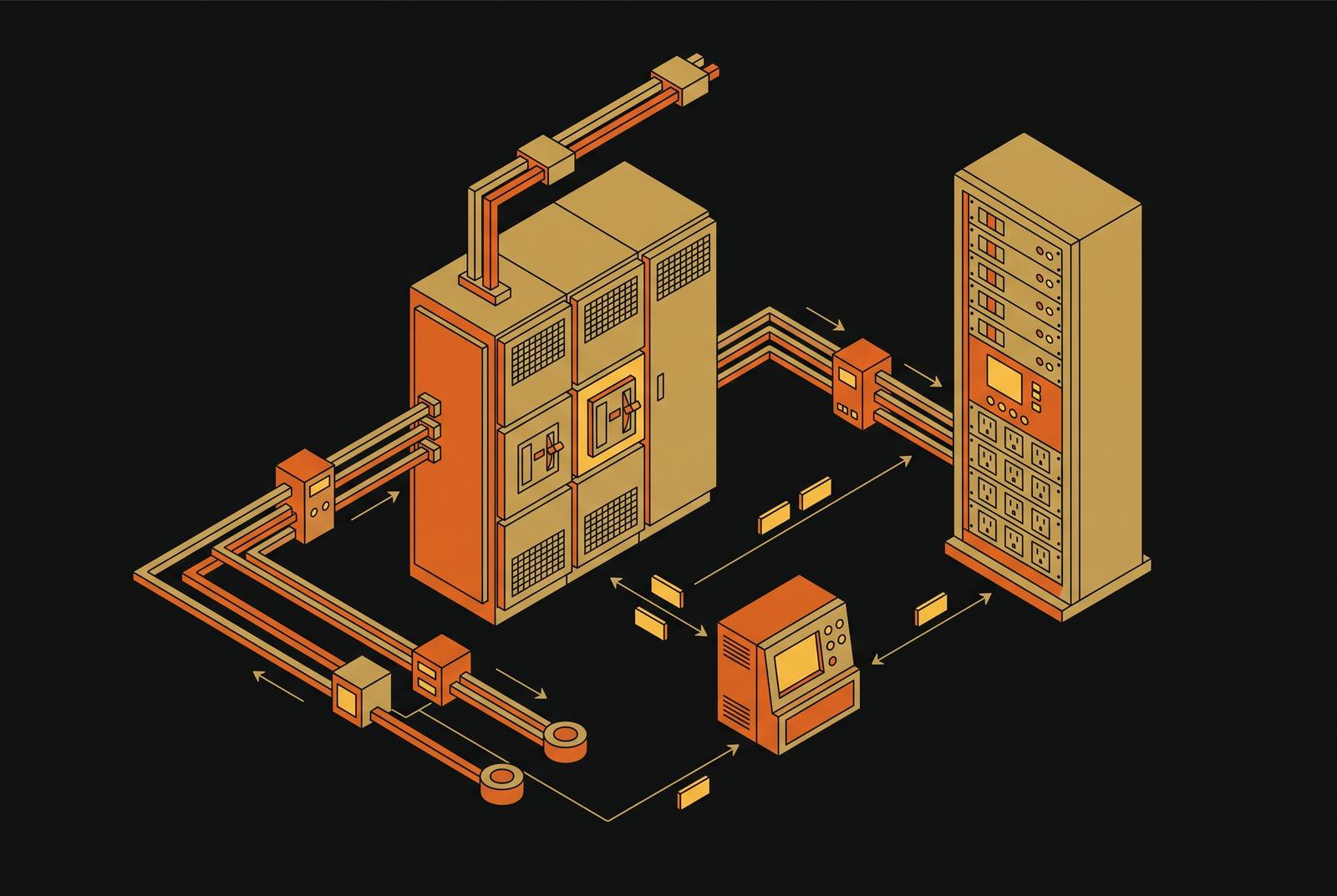
A DCIM-ready design model handoff starts with structured asset data in the design model so the data does not have to be entered again by hand at turnover. For EPMS integration, switchgear and PDU requirements must define meter points, naming conventions, CT ratios, circuit topology, and communication parameters before equipment is ordered. Those attributes must flow into the points list and handoff package so commissioning verifies the monitoring hierarchy.
Why the EPMS metering hierarchy fails when device data is undefined at design time
Meters must reconcile as linked nodes in a power chain. That chain runs from the utility entrance through main switchgear bus and feeders, generators, UPS input and output, PDUs, and branches. Each stage needs the data that connects its readings to the levels above and below it. A gap does not stay at one meter. When levels do not add up, the cause is a metering error or an unmetered load, and an unmetered load is capacity nobody is tracking.
Every node must expose the required attributes in a consistent structure so the EPMS can place its readings in the hierarchy. A device that exposes voltage and current but not required power factor data leaves an incomplete view. A circuit name that differs from the expected point-list tag breaks the association between the reading and its place in the chain. Both failures start in the specification before they affect monitoring.
Those gaps also pass into the systems that consume EPMS data. The EPMS owns the electrical train and power quality, while the BMS owns the mechanical plant. DCIM consumes data from both systems without replacing either. It needs the missing device-level data to complete the electrical hierarchy. The design must establish that hierarchy before downstream systems can use it reliably.
What the metering one-line and points list must commit to before equipment is ordered
The metering one-line and points list commit the owner and equipment supplier to the same monitoring requirements. Together, they establish which physical devices have meters, which attributes each meter exposes, and where each attribute belongs in the EPMS hierarchy. That commitment belongs before equipment is ordered. Once equipment ships, the project is working with the hardware and configuration already chosen.
The owner's operational need determines where the one-line places meters. A colocation provider billing tenants needs metering at each tenant's power boundary. An enterprise that tracks PUE needs meters at the points used in that calculation, while a plant that needs fault diagnosis must see more of what happens at the switchgear and UPS. These are different reasons to choose a metering boundary. The points list must turn the chosen boundary into specific device requirements rather than leave the supplier to infer what the owner intends to measure.
Equipment ordered without confirmed meter specifications can arrive with default firmware, point names, and CT ratios that do not match the EPMS design. Correcting those defaults requires field rework or factory return. Metering-compatible switchgear and routes for low-voltage data cables must also be chosen during design, because changing the configuration during commissioning cannot create a physical path that is missing.
The one-line establishes the power chain, and the points list commits each device to its part in that chain. Both must be read before commissioning begins. The hierarchy shown in the design is the hierarchy the commissioning team must prove reconciles.
The specific data attributes switchgear must expose at every level of the distribution hierarchy
Main and distribution switchgear must be specified for EPMS data exposure as well as protection and control. The measurements must include three-phase bus voltage, both line-to-line and line-to-neutral, and feeder current per phase. The EPMS also needs real power in kW, reactive power in kVAR, apparent power in kVA, and power factor. These are distinct requirements. A general promise of “metering” does not commit the supplier to expose all of them.
The specification must also call for energy in kWh for billing and PUE calculation, as well as peak and rolling demand for capacity planning. Every monitored breaker must show whether it is open, closed, or tripped. Together, bus voltage, feeder loading, and demand help with capacity assessment and fault diagnosis at the top of the distribution chain. When attributes are missing, gaps remain even if protection works as it should.
CT ratio must match the meter's input range and be recorded in the points list. This is a design commitment. A mismatch creates a scaling error that propagates through energy and PUE calculations using that meter's output. During commissioning, each meter must then be checked against a reference because its configured ratio alone does not prove that it is accurate. During that work, a CT secondary must never be opened on an energized circuit, and the short must be made at the shorting block first because an open secondary builds dangerous voltage.
The switchgear submittal must specify Modbus TCP/RTU, IEC 61850, or BACnet IP to match the EPMS platform's native driver. IEC 61850 is an option with a network-health dependency that requires a defined communication design. The device address or node ID must be assigned in the points list and factory-configured before shipment. Polling intervals must meet the design's fault-detection requirements, and time-synchronized event recording must be accurate to the millisecond for root-cause analysis after a disturbance. These settings cannot be left to field negotiation.
The names must be agreed during design and used in the factory firmware. A default tag such as “Meter_001” does not satisfy a points list expecting “MSB-A-FDR-04-kW.” Correcting that mismatch can cascade through alarm configurations, trend logs, and report templates. The same physical device must have the same identity in the single-line diagram, points list, and DCIM asset register. That identity must remain traceable as the hierarchy descends to PDUs and branches.
The specific data attributes PDUs must expose to extend EPMS visibility to the branch circuit
A PDU tag must give the device a unique name and show where it sits in the distribution hierarchy. It must encode which switchboard feeder supplies it and which data hall row it serves. Branch circuit tags must then name the PDU parent and circuit number in a way that matches the DCIM rack numbering scheme. The parent relationship is part of the requirement. Without it, operations must manually connect a branch reading to the power chain it belongs to.
PDU input metering must expose per-PDU load and energy, while branch metering must expose per-rack or per-circuit current and power. The branch view identifies a circuit approaching its rating before its breaker trips. That is the operational reason to extend monitoring below the PDU input. Without branch-level requirements, staff must walk the floor to manage capacity beyond the distribution edge because they cannot get that view from the system.
The PDU communication path must also be specified before the equipment is bought. Intelligent PDUs communicate over Modbus TCP, SNMPv3, or, in newer deployments, Redfish, but the installer should not be choosing the protocol. SNMPv3 is common for rack PDUs feeding DCIM, while the EPMS may need a separate Modbus or BACnet path to match its drivers. Both paths must be specified when both are required. Device addresses, the applicable community string or credential, and polling intervals must be factory-configured and documented in the handoff package.
If the EPMS and DCIM use different names for the same branch, the current measurement may be available but its operational context is unreliable. A near-trip indication is useful only when the circuit can be traced to the right location and rack. That connection makes naming and topology cross-system requirements.
How do naming conventions and circuit topology connect a BIM handoff to EPMS, DCIM, and BMS?
A hierarchy can reconcile inside the EPMS and still fail to support cross-system operations. That happens when its names or circuit relationships differ from those in the DCIM asset register. DCIM holds the asset register, rack elevations, power chain, and capacity model, all of which refer to physical devices monitored elsewhere. It consumes electrical data from EPMS and mechanical data from BMS.
A branch approaching its rating makes the consequence concrete. If its EPMS tag differs from its DCIM identity, an operator needs a lookup table to find the associated rack. Someone must maintain that translation by hand. The same need to translate affects decisions on capacity and change-management when systems describe the same physical circuit in different ways. Consistent names remove that translation step, while consistent topology establishes how the circuit connects to the rest of the power chain.
For a DCIM-ready design model handoff, the connected design workflow defines equipment tags, CT ratios, communication parameters, and circuit topology once as structured model data. Those attributes then flow into the points list and handoff package. The single-line diagram, EPMS points list, and DCIM power chain must encode the same circuit topology, because commissioning agents, operators, and DCIM administrators approach the same device from different starting points.
The formal digital asset handover must also record the physical location, IP addresses, calibration data, and communication parameters. These fields link the design's naming convention to the installed equipment and its operational connections. They are not details to collect after integration fails. Whether structured data can flow from the model into operational systems is a design-phase decision. Leaving that decision until turnover means rebuilding the integration when the project should be verifying it.
What commissioning must verify—and what it cannot fix—when data requirements were not defined at design
Commissioning must test the specified hierarchy against the installed system. Every meter must be checked against a reference, and the check must confirm that its CT ratio is accurate. Point-to-point testing must follow every monitored point from the field device to the EPMS screen and check that its tag, engineering unit, scaling, and alarm threshold are correct. A meter that is turned on but has not been checked against a reference is not commissioned.
The tests must also prove that the levels reconcile. Utility entrance readings must be summed and compared with switchgear feeders, UPS output, and PDU inputs to confirm that the hierarchy closes. Sequence-of-events timestamps must be checked for millisecond accuracy because root-cause analysis needs them to be in the right order. Polling intervals, protocol configurations, and device addresses must be checked against the points list.
A CT factory-wired to the wrong tap because of an incorrect submittal requires factory return or field modification with documented re-verification. Unsupported protocol firmware requires an update or hardware substitution, compressing the commissioning window. Naming mismatches require remapping that grows with the points list. Missing PDU or branch metering requires physical hardware installation and may require an outage, so commissioning cannot absorb the omission as a routine settings change.
The cause-and-effect record, as-left settings archive, and baseline dataset show operations how the installed EPMS was configured. Their value depends on accurate requirements followed through design, procurement, and testing. With that chain intact, the operations team receives a usable hierarchy on day one.