Cable and Fiber Route Data Models for Operations-Ready Documentation
Structured route data models ensure fiber and cable installations handoff operations-ready on Day 1.
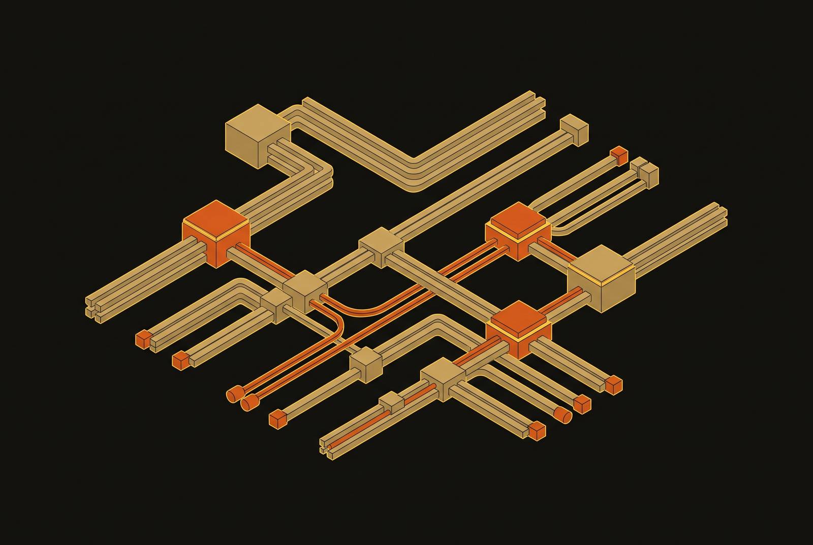
DCIM-ready BIM handoff requires cable and fiber route data models built as structured, connected records from the first design decision. Those records must link the physical routes, logical endpoints, test results, and shared asset identifiers so operations can query them on Day 1. ArchiLabs Studio addresses this gap by connecting design, routing, engineering decisions, and operations-ready handoff in one workflow.
Why fiber density in AI-era data centers makes route documentation a precision-engineering problem, not a records-keeping task
An AI rack requires far more optical fiber than a conventional server rack in the same footprint. R&M USA’s hyperscale fiber analysis describes AI fabrics with trunks containing orders of magnitude more fibers than prior-generation hyperscale planning assumed, with far more connectors per side and multiple fiber channels per connector. Each connection needs a precise, traceable identity. A route drawn between two racks does not, by itself, explain those connections.
This density changes what documentation has to prove. Fiber count, cable tray sizing, and power distribution architecture must be worked out together during design so the planned infrastructure can support the equipment it serves. A single planning error can strand massive GPU investments at a fraction of their potential utilization. Documentation therefore has to preserve the engineering relationships behind the installation along with the cable’s location.
How the procurement shift toward factory-built assemblies moves documentation burden upstream — and what happens when the data doesn't follow
Factory-built, pre-terminated, fully tested assemblies are a sound way to meet this need for precision. R&M’s analysis describes a shift from field termination to assemblies that are made to specification, labeled, and delivered ready to install. This cuts the need for scarce specialist labor and takes much less time to install. The documentation work moves to the factory, where fiber counts, connector polarity, and label assignments are fixed before installation begins.
The route data model must be ready to receive those decisions at procurement. If manufacturer records remain in supplier PDFs, the operations team can inherit tested hardware without traceable topology. The test establishes the assembly’s physical performance, while the missing links leave its logical and spatial relationships unresolved. Pre-termination delivers its documentation benefit only when the factory data flows forward with the hardware.
Pathway-first installation makes that distinction even more important. R&M also describes microducts and blown fiber, where operators install pathways first and add fiber as architectures change. The pathway and its contents are different records. When those records are linked, the model can show new fiber without rebuilding the record of the conduit already installed.
Why cable and fiber route data cannot be modeled in isolation from power and cooling at the rack level
At the rack, fiber routes use the same physical space as power distribution and cooling pathways. These systems compete for the same overhead space, and their requirements must be resolved together. Cable topology alone is therefore an incomplete design boundary. It can describe a connection without establishing whether the route fits its electrical and thermal surroundings.
A cable tray model can be clash-free and still fail to account for power segregation requirements. In that case, the absence of a geometric clash does not establish that the route is acceptable. Routing conflicts may become apparent only during installation, when they cost the most to fix. The model needs more than coordinates and endpoints. It must keep the power and cooling context that made the rack-level route work, so later changes can be checked against those same constraints as well as cable geometry.
What the TIA-942-C and BICSI 002-2024 standards actually require from route data, and where standard compliance ends and operational readiness begins
TIA-942-C establishes the minimum framework for cabling infrastructure, while BICSI 002-2024 provides best-practice guidance. BICSI’s coverage also includes electrical systems, mechanical systems, liquid cooling, and DCIM integration. Neither standard, however, substitutes for the structured, connected records needed to query a route model on Day 1.
TIA-606 establishes identification requirements, including source-destination labeling and documentation of cable identifiers. Color-coding is optional but recommended. But a labeling standard is not a data schema. A correctly labeled cable in a PDF schedule may meet the identification requirements, but an operator may still have to look up its connections by hand.
A facility can be TIA-942-C compliant and BICSI 002-2024 aligned without letting an operator ask which fiber connects to which rack port and receive a direct answer. That establishes a separate delivery obligation, which is to make the installation’s identifiers, routes, and connections accessible as linked data.
How can structured asset data get from BIM into DCIM without manual re-entry?
BIM resolves spatial conflicts among busway, chilled water piping, cable tray, and fire suppression during design. But geometry is only part of the handoff. A clash-free BIM model without structured asset data leaves operations with a solved spatial problem and an unresolved information problem.
The workflow itself can span several tools. Revit may handle authoring, Navisworks or BIM 360 coordination, and Bluebeam or Procore document workflows. Information can be lost between them unless exchange formats and processes are managed carefully. Delivering the final model does not prove that the receiving DCIM system can interpret its asset records or connect them to operational data.
Before construction begins, the project needs to align the schemas and agree on how to share asset identifiers. That work must spell out how design records map to the records DCIM needs, because a closeout export cannot be expected to create those links. Design-to-as-built reconciliation must then follow a formal workflow with defined acceptance criteria. A DCIM-enabled digital twin depends on this exchange architecture, and retrofitting integration after handover is significantly more expensive and rarely complete.
The naming collision and system boundary problems that make an unresolved identifier strategy an operational liability
The BMS calls a unit CRAC-02-DH2, the EPMS calls its supply circuit DB-2A/14, and DCIM calls the space DH2-Row-C. These names describe related parts of the installation from different system viewpoints. Without a mapping, the relationship remains unresolved for operators. A precise cable route cannot compensate for uncertainty about the asset, circuit, or space at its end.
Each system has a distinct job. The BMS identifies mechanical and environmental plant, while the EPMS monitors the electrical path from utility incomer to rack. DCIM manages the IT assets, rack space, power capacity, and network connectivity. It consumes data from the other two systems. Unresolved identifiers can therefore leave blank fields and mislead operators across system boundaries.
The problem persists because integration can fall into a scope vacuum. The mechanical contractor delivers the BMS, the electrical contractor delivers the EPMS, and the client’s IT team buys DCIM. Each system can be signed off on its own while no one takes charge of the links between them. The remedy is a shared naming convention that maps system identifiers to the same physical assets and their relationships before construction begins. Identifier resolution must be a formal handoff acceptance criterion.
What a route data model that answers operational questions on Day 1 actually looks like in structure and practice
An operations-ready route model consists of queryable records for cables, pathways, connectors, and associated assets. Each cable identifier links to its physical route, including tray segments, a bend-radius-compliant path, and separation zones. It also links to logical endpoints, including the relevant rack, port, circuit, and asset. The record includes fiber count and type, connector polarity, test results, and the BMS, EPMS, and DCIM identifiers for connected assets.
Compliance information belongs in that same structure. TIA-942-C topology zones, namely MDA, IDA, HDA, ZDA, and EDA, must be route properties. BICSI 002 power-data separation minimums and fill compliance must likewise be queryable attributes so changes can be validated against the route’s requirements. A static note cannot serve the same purpose without someone reading and interpreting it again.
Cable tray, microduct, and conduit records link to the fiber or copper within them, so a pathway can exist before its media is installed. Manufacturer test results, connector assignments, fiber counts, and labels go into the model at procurement, which avoids copying them in at closeout. Each deviation from the designed route becomes a linked change with defined acceptance criteria. Together, these relationships provide the concrete target for a handoff that operations can query, update, and reconcile without manual lookup or re-entry.
How deterministic rules and AI each have a defined role in building and maintaining route data models — and why confusing them produces the wrong kind of automation
Deterministic rules belong wherever the model must make a repeatable compliance judgment. Fill ratios, separation minimums, labeling, and compliance constraints need explicit validation rules. AI-assisted analysis has a different role, including routing optimization, conflict surfacing, and procurement alignment. These are different kinds of engineering work. Treating them as interchangeable weakens both the search for better routes and the basis for accepting them.
The order of application is critical. If AI-assisted layout runs before compliance constraints are encoded, it can suggest routes whose geometry is optimized but which break fill limits, separation requirements, or labeling standards. Adding the rules later requires retroactive validation of every generated route. The correct sequence is to encode deterministic constraints on route records first, then filter AI-surfaced options against those requirements in real time.
Neither form of automation removes engineering responsibility. Licensed engineers still decide whether a clash resolution is structurally sound, a maintenance sequence is practical, or a deviation from design is acceptable. Automated compliance checks show whether the encoded conditions are met. They do not grant approval for every engineering consequence of a proposed change.
Why building the route data model from the first design decision — rather than assembling it from construction redlines — changes what operations teams inherit at Day 1
Construction redlines record changes, but they cannot by themselves reconstruct the full basis for those changes. A route model assembled from them is a retrospective approximation unless the design intent, procurement records, and validation history have been preserved elsewhere and reconciled. Informal closeout reconciliation leaves deviations without a dependable explanation. Operations then inherits uncertainty with the drawing. The cost is not just missing history, but doubt about which records can support a current decision.
A continuously built model preserves a different chain of evidence. It starts with the original fiber-count and tray-sizing arithmetic, keeps the compliance validation from each design stage, and adds pre-termination data at procurement. RFI and submittal decisions remain connected to the routes they altered. As-built confirmation then establishes that each segment was installed and tested as documented.
Studio is purpose-built around this continuous workflow, connecting layouts, cable routing, critical-systems engineering, RFIs, and operations-ready handoff. Its role is to bring a traceable record to DCIM, EPMS, and BMS integration. The operational test is direct. On Day 1, can staff identify which fiber connects to which rack port, which circuit feeds which rack, which test result applies to which assembly, and which design decision produced the current route? If an answer requires a phone call to a contractor, the handoff has transferred an unresolved operational liability to the owner.