Cross-Domain Constraint Re-Evaluation as the Differentiating Architecture in Capital-Facility Configurators
Shared constraint models catch physics-coupled failures that separate rule sets miss.
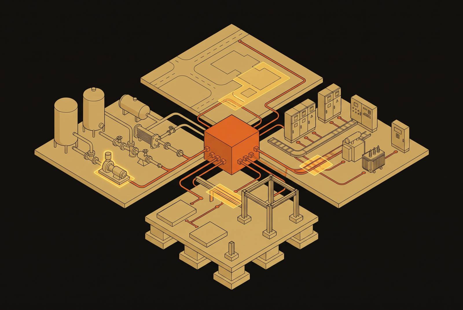
Automated change propagation after a rack move requires a shared model that re-evaluates power, cooling, structure, cabling, schedule, and documentation together. In capital-facility configurators, that architecture matters more than the length of the rule list as a differentiator. ArchiLabs Studio positions this connected workflow as its approach, with structured handoff to DCIM, EPMS, and BMS.
Why capital-facility configurators face a different problem than standard product configurators
Buyers know where to start with a car, software bundle, or enterprise SaaS configurator. Select a base product, choose options, and validate the combination against compatibility and commercial rules. A capital facility presents a different problem. Its engineering systems are coupled by physics, so a valid choice in one system can make another system infeasible.
For example, selecting a higher-density GPU rack changes more than the equipment specification. It changes the floor loading, the cooling requirements, the power distribution sizing, and the construction sequence that depends on those systems. A power calculation can pass while the floor rating fails, leaving a design that is locally valid but globally wrong.
What cross-domain constraint re-evaluation actually means architecturally
Cross-domain constraint re-evaluation means that changing an input triggers a joint recalculation of every constraint coupled to it. It is not simply running several separate rule sets. The architecture keeps a shared constraint graph, a model in which nodes stand for design parameters and connections show how they depend on one another. A change follows those connections to the affected calculations. Unrelated parts of the design need not be recalculated.
The distinction becomes clear when power and cooling interact. Available power headroom limits which cooling arrangement is feasible, but that arrangement also consumes power through auxiliary equipment. The dependency runs in both directions at once. Checking power, then cooling, without revisiting power can leave the first result invalid. A solver, the calculation system that finds a combination satisfying the constraints, must resolve that loop jointly.
Shrenik Jadhav, Vidhyashree Nagaraju, and Zheng Liu’s Data Center Life Cycle Co-Design Optimization applies this reasoning to the Frontier supercomputer cooling plant. Its framework brings together operational energy, embodied carbon, capital cost, and reliability expressed through expected unplanned downtime. Reliability policy changes which cooling subloop architecture is acceptable, so it must shape the design as well as add a score to it. A subloop is a parallel branch of the cooling plant that serves coolant distribution units. Optimizing cost and carbon without that policy can select a topology that operations cannot accept.
How AI-era rack density collapsed the margin that legacy configurators depended on
Low, relatively uniform rack loads left room for imperfect coordination between engineering domains. If the cooling estimate was a little too low, spare capacity in other systems could keep that error from forcing a structural redesign or changing the construction sequencing. AI workloads use up that margin in several systems at once. Rack weight pushes close to floor ratings, while liquid cooling changes what is needed for plumbing, clearance, and auxiliary-power requirements.
Power quality makes the problem especially concrete. GPU power supplies generate harmonics, which are distortions in the electrical current that can concentrate in the neutral wire. Under these loads, standard utility substation transformers need de-rating because their usable capacity is lower than their nameplate rating. IEEE C57.110 provides methods for calculating transformer capacity under harmonic loading. The label alone is not a sufficient capacity check.
A configurator that raises GPU rack density but continues comparing demand with nameplate transformer capacity can overstate the power available to the facility. Its arithmetic may be right even if the capacity it assumes is wrong. This is an architecture problem. Equipment selection must be connected to the calculation of effective transformer capacity, which must then feed the remaining power and cooling decisions. Without that connection, adding a harmonic-loading rule somewhere in the system does not make changes propagate to it.
What fails when a rack move does not update power, cooling, cabling, and documentation?
Capital-facility design does not stop changing after the first valid configuration. Equipment substitutions occur, site constraints shift, and client requirements develop throughout the project. A rule-list architecture validates a snapshot, leaving those dependencies unmaintained. When an input changes, previously generated outputs can remain stale while still appearing approved. The failure is often a confident answer.
A rack-model change exposes the reach of that failure. The affected calculations can include floor loading, cooling loop sizing and subloop assignment, power distribution capacity, transformer de-rating, and cable or busbar routing. Changes to equipment can also change delivery lead times and construction sequencing. A BIM layout update alone does not establish that these dependencies were recalculated. If the associated schedules and engineering outputs remain disconnected, the inconsistency may become visible in coordination drawings, submittals, or fabrication releases only after they have been issued.
The Frontier analysis shows why a configuration solved at project inception cannot simply be treated as final. Introducing a reliability constraint changes the acceptable subloop optimum. That is distinct from sensitivity to physical grouping. The co-design framework found that optimized flow fractions made the result robust across feasible groupings of coolant distribution units. The architecture must distinguish consequential dependencies from changes the design can absorb.
What the constraint graph must span to be complete for a capital facility
The power model must include more than rack demand and a capacity total. It needs available grid capacity, interconnection headroom, transformer effective capacity, UPS and PDU sizing, busbar routing and capacity, and cooling auxiliary loads. The cooling model must connect rack heat loads to topology choices, including air, direct-to-chip, rear-door, and immersion cooling. It must also represent coolant distribution units, subloop assignments, and chiller and CRAH/CRAC sizing.
Structure must be modeled at the rack position. The load includes IT equipment, cabling, in-rack coolant distribution units, and coolant reservoirs, assessed against the raised-floor or slab rating. Liquid cooling also needs pipe runs, manifolds, and clearance requirements that an air-cooled layout does not have. Moving a rack therefore changes more than its coordinates. The model must connect its new location to the relevant loading and cooling-infrastructure constraints.
Schedule belongs inside the same dependency model. Transformer, switchgear, and cooling-plant lead times depend on the equipment selected, while fabrication releases depend on submittal clearance and trade sequencing. Siting adds another coupling between power availability and interconnection feasibility. Kim, Dong, and Xie’s data center siting research formalizes reliability-gated screening and flexibility-envelope requirements that a feasible site may need to meet. A technically acceptable equipment configuration cannot settle those conditions by itself.
The graph must also reach the operational handoff. BMS and EPMS point lists, cable schedules, single-line diagrams, and equipment datasheets all draw from design decisions and must match the as-configured facility. These documents represent the same equipment, connections, and constraints. If this layer is left out of the model, the operator has to piece it back together.
Why the handoff from design configurator to operational systems is where constraint re-evaluation earns its cost
A construction BIM model is not automatically an operational asset model. The operator’s model format, asset tagging structure, and data requirements for maintenance-management and DCIM systems need to be defined at project kickoff if operational BIM is an objective. Handover is too late to establish that foundation. Without it, the operator may need substantial rework before the construction model can support facility management. A connected design process can instead preserve the required structure as the facility evolves.
That is where the value compounds across iterations. When the configurator maintains consistent equipment and dependency data, the handoff package becomes a generated output of the design process. Without that continuity, someone must trace drawings, spreadsheets, and submittals to reconstruct the point lists, cable schedules, diagrams, and datasheets. Each document may describe a different stage of the project. Reconstruction therefore means collecting the files and working out which information matches the final configuration.
DCIM depends on information from both facility and IT systems. Its facility inputs include UPS equipment, PDUs, CRAC and CRAH units, chillers, and BMS sensors. Seeing assets together cannot fix links between them that are missing or inconsistent at handoff. The usefulness of the operational view is bounded by the completeness and quality of the supplied data.
How ArchiLabs Studio implements cross-domain re-evaluation as a project operating system
ArchiLabs Studio describes its approach as a connected project workflow in which rack moves, equipment substitutions, and scope changes cascade through engineering and documentation. It brings layout, critical-systems engineering, cable routing, RFI management, and operations-ready handoff into that workflow. The target is the break between disconnected tools. If a layout changes while cable schedules and system calculations remain untouched, the project has updated one view while its underlying configuration remains unchanged.
AI helps accelerate responsive work and surface configuration options, while deterministic rules govern decisions where precision and compliance are non-negotiable. A safety constraint cannot depend on whether a probabilistic model chooses to follow it.
ArchiLabs extracts information such as thermal loads, clearances, and load-bearing limits from manufacturer PDFs into models, schedules, and validation rules. That addresses the gap between what equipment demands and what the design assumes. RFI and submittal management sit in the same workflow, making answers and design decisions traceable to supporting constraint information. The operational handoff then uses the maintained BIM and asset data.
This positioning connects established tools. DCIM, EPMS, BMS, and BIM retain distinct roles. ArchiLabs treats structured handoff to the operational systems as the design workflow’s finish line. Its claim is therefore broader than updating rack records inside a single application. It addresses the design-to-operations chain in which a physical change must remain consistent across calculations, routing, documentation, and asset data.
What to look for when evaluating whether a configurator actually re-evaluates across domains
The practical evaluation follows directly from these failure modes. Both a shared dependency model and a broad rule list can produce convincing outputs for an unchanged design. The first test is therefore a controlled change. Move a rack or alter its IT load, then ask whether the system re-evaluates the affected power, cooling, structural, cable-routing, and documentation outputs without separate domain-by-domain reruns. A changed layout is not evidence that its dependencies changed.
The second test is bidirectional coupling between power and cooling. Does cooling auxiliary demand use up available power headroom, and does having less headroom change which cooling options can work? Both directions need to be visible in the result. The third test draws on the Frontier distinction: redundancy or reliability policy is changed to check whether the cooling subloop architecture is re-evaluated. A tool that cannot express that policy as a constraint is solving a narrower problem than the facility requires.
Substitute power or cooling equipment and ask whether procurement lead times and fabrication-release dependencies update with the engineering selection. A technically valid substitution may still be schedule-infeasible. The fifth test combines handoff completeness with traceability by requesting generated BMS and EPMS point lists, cable schedules, single-line diagrams, and equipment datasheets, then tracing design decisions and RFI answers to their supporting constraints.
One changed input must reach every dependent calculation and record without forcing the team to rebuild the links by hand.